ATX to RPS
English below
Dutch 'research'
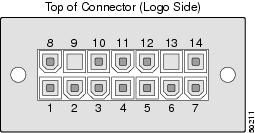
1 GND
2 -48 V
3 12 V
4 12 V
5 12 V
6 12 V
7 GND
8 GND
9 -48 V
10 RPS_PRES (RPS present)
11 RPS_CTRL 0
12 RPS_CTRL 1
13 PWR_GOOD (power is good)
14 GND
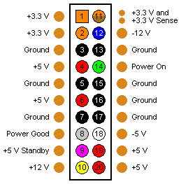
Als je van een 20-pins ATX connector de 6 meest rechtse pinnen weghaald zou hij moeten passen (fisiek). Je zal dan nog wel wat bedrading moeten aanpassen gezien de pinouts helemaal niet kloppen.
Als 1e test ga ik +12v op pin 3 t/m 6 zetten en de GND op 7, 8 en 14. Update: Omdat een ATX voeding standaard maar 1 12V pin heeft heb ik slechts 2 van de 4 12V pinnen aangesloten. Ook heb ik maar 2 GND pinnen gebruikt gezien deze intern toch door zijn verbonden (was te zien op de voeding)
De volgende kabel heb ik gemaakt:
ATX         RPS
7 --> GND --> 7
          \-> 8
10 -> 12V --> 3
          \-> 4

14 -> PON -\
15 -> GND -/
Pin 14 en 15 zijn onderling verbonden zodat de ATX voeding start. Verder heeft de RPS aansluiting alleen +12V en GND nodig. De c3750g waarmee ik heb getest start prima, ik meet 11.4V op de plug met een 300watt ATX voeding (welke 13A zou moeten kunnen leveren op 12V) en de switch lijkt prima te functioneren. Ik heb nog geen duurtesten gedaan en/of load testing (alle interfaces gebruiken) maar het is erg aannemelijk dat dit gewoon blijft werken.
English summary
I had a Cisco 3750g switch which had a few bad capacitors (known issue in the 1,5u models?). After replacing them, the switch still wouldn't show any sign of life. Apparently the PSU was dead too (which came first? bad PSU or bad capacitors?) because after swapping the PSU with a working model the switch lit up just fine.
A new power supply is a bit costly so I decided to investigate the RPS connector first. The size looked a bit like an ATX connector and after further inspection it seemed you could even fit (part of) an ATX connector.
After that is was a matter of hooking up an ATX PSU to the RPS port and see what happens.
It booted just fine, that's what happened.
So how to make such a 'converter'? Just cut off the 6 pins on the outer right side of the ATX connector and it will fit the RPS connector. Remove all excessive wiring and connect the 12V and GND to the correct pin:
ATX         RPS
7 --> GND --> 7
          \-> 8
10 -> 12V --> 3
          \-> 4

14 -> PON -\
15 -> GND -/
Connect pin 14 and 15 from the ATX PSU to each other so the PSU will start.

